Welcome to Decade Engineering!

We manufacture low-cost video OSD (On-Screen Display) modules and other function blocks for use by system designers. OSDs often serve as graphics and character overlay generators for data display in remote video inspection systems, security systems, and remotely piloted vehicles (UAV, ROV, RPV) or robots. They can also be used as industrial video titlers, dumb serial terminals, and TV-based information displays or electronic signs.
Featured Products
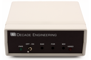
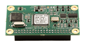
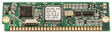
XBOB-4 expands Decade's fourth-generation OSD technology into a convenient freestanding format. The command set is identical to that of our popular BOB-4 modules. XBOB-4 provides low-cost video CG (character generator) functionality, letting your PC display text and vector graphics on standard TV monitors. With large user-definable character sets, XBOB-4 also supports bitmap graphics and multiple languages.